Cat 6 Poe Camera Wiring Diagram / Ip Camera Wiring Diagram Cornick. It reveals the parts of the circuit as simplified forms, and also the power and also signal connections in between the devices. Some other cameras may vary in their pin layout. Orange & white pin 2: Assortment of cat5 cctv wiring diagram. Last year i completed a project in my house to wire most of it with cat 6 ethernet cable.
Wellborn collection of cat 6 wiring diagram rj45. This diagram features 16 cameras connected directly to the admiral nvr. Wed oct 14, 2015 2:20 pm. As external power doesn't needed in poe ip cameras, therefore connect only the cameras through poe via cat5 / cat 6 cables. Otherwise, the structure will not work as it should be.
Best Cctv Cable For Analog Hd Cameras And Ip Cameras Cat6 Cable To Use Both Hd Analog And Ip Camera Youtube from i.ytimg.com To connect a new connector (rj45 jack) to the hikvision ip camera refer to the diagrams below. So we attempted to uncover some good poe cat5 wiring diagram graphic to suit your needs. Green & white pin 4: A wiring diagram is a simplified traditional photographic representation of an electrical circuit. Wed oct 14, 2015 2:20 pm. The camera uses one pair to talk to the nvr wire #1 and #2. Pins 2 and 3 transmit data to and from the camera. The picture below shows the tp link poe injector that can be used to power up ip cameras using the international standard ieee 802.3af for up to 100m.
It reveals the parts of the circuit as simplified forms, and also the power and also signal connections in between the devices.
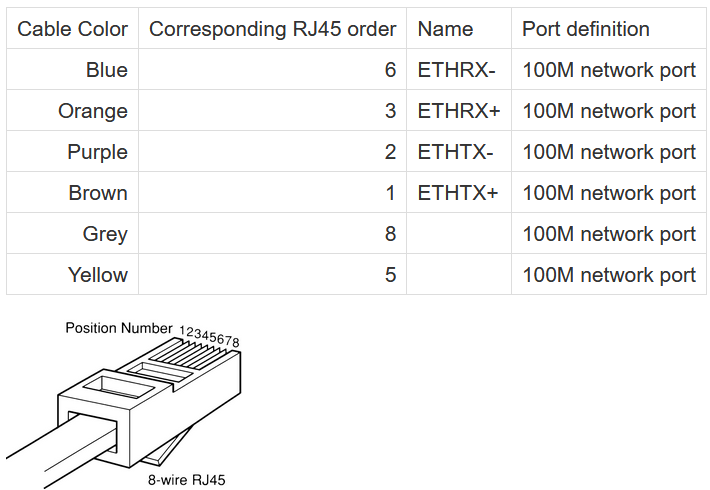
To connect a new connector (rj45 jack) to the hikvision ip camera refer to the diagrams below. Blue & white pin 6: October 9, 2018 by larry a. Below is a description of the basic functionality of each wire associated with the ethernet port pins these cameras: Truly, we have been realized that poe cat5 wiring diagram is being just about the most popular field right now. Pins 2 and 3 transmit data to and from the camera. Otherwise, the structure will not work as it should be. The 32 channel admiral pro has the ability to support 32 ip cameras, but only has 16 poe ports on the back. Cat5 enhanced(cat5e) replaced the traditional cat5 cable and introduced speeds up to ten times faster than cat5 cable. Wed oct 14, 2015 2:20 pm. This article explain how to wire cat 5 cat 6 ethernet pinout rj45 wiring diagram with cat 6 color code , networks have become one of the es. Lan connections/pinouts are defined by ieee u. Currently, 2 types of wiring are widely used for ip security cameras which are cat6 or cat5e twisted pair cabling.
Here is my understanding of ip cameras and cat5: Otherwise, the structure will not work as it should be. This article explain how to wire cat 5 cat 6 ethernet pinout rj45 wiring diagram with cat 6 color code , networks have become one of the es. Poe outdoor cam rj45 cable pinouts. You can use passive poe splitter and poe injector and the wire length can be 130 feet (40 meter).
Cat6 Camera Wiring Diagram from i0.wp.com This is achieved by increasing the wire twists, better shielding, drain wire, and increased wire diameter. Last year i completed a project in my house to wire most of it with cat 6 ethernet cable. The 32 channel admiral pro has the ability to support 32 ip cameras, but only has 16 poe ports on the back. Find out cat 5/cat 6 security cameras/systems, ethernet security camera, how to wire cctv cameras over cat 5 cable and ip camera wiring diagram. It reveals the components of the circuit as simplified shapes, and the power as well as signal connections in between the devices. It reveals the elements of the circuit as simplified shapes, and also the power as well as signal links between the tools. To connect a new connector (rj45 jack) to the hikvision ip camera refer to the diagrams below. So we attempted to uncover some good poe cat5 wiring diagram graphic to suit your needs.
Orange & white pin 2:
Assortment of cat5 cctv wiring diagram. This is achieved by increasing the wire twists, better shielding, drain wire, and increased wire diameter. A wiring diagram is a streamlined standard photographic representation of an electrical circuit. Green & white pin 4: Can you send me the diagram? You can use passive poe splitter and poe injector and the wire length can be 130 feet (40 meter). In most cases you run your video and power to and from the camera on the same cat5 or cat6 wire, assuming you are using a poe (power over ethernet) power source such as a poe injector or poe switch. Truly, we have been realized that poe cat5 wiring diagram is being just about the most popular field right now. Each part ought to be placed and linked to different parts in particular way. The nvr uses another pair to talk to the camera wire #3 and #6. Poe camera wires to cat 5/6 connector (t568b) for these camera models. It reveals the parts of the circuit as simplified forms, and also the power and also signal connections in between the devices. 06:58 2 comments one cannot imagine living without networks in the present times.
It reveals the components of the circuit as simplified shapes, and the power as well as signal connections in between the devices. Can you send me the diagram? Poe camera wires to cat 5/6 connector (t568b) for these camera models. This article explain how to wire cat 5 cat 6 ethernet pinout rj45 wiring diagram with cat 6 color code , networks have become one of the es. Below is a description of the basic functionality of each wire associated with the ethernet port pins these cameras:
Ip Camera Wiring Diagram Cornick from static.helpjuice.com You may follow the wire order below to arrange the wires of your rj45 connector. Find out cat 5/cat 6 security cameras/systems, ethernet security camera, how to wire cctv cameras over cat 5 cable and ip camera wiring diagram. Brown & white pin 8: Green & white pin 4: Otherwise, the arrangement will not function as it should be. I had two damaged cameras but the solutions here did not work for my camera models. This is what worked for me. Cat5 enhanced(cat5e) replaced the traditional cat5 cable and introduced speeds up to ten times faster than cat5 cable.
Some other cameras may vary in their pin layout.
So we attempted to uncover some good poe cat5 wiring diagram graphic to suit your needs. Ip needs 2 pairs of wire to communicate with the nvr. See how i did it with lots of pictures. Currently, 2 types of wiring are widely used for ip security cameras which are cat6 or cat5e twisted pair cabling. Orange & white pin 2: You can use passive poe splitter and poe injector and the wire length can be 130 feet (40 meter). This diagram features 16 cameras connected directly to the admiral nvr. Wellborn collection of cat 6 wiring diagram rj45. To connect a new connector (rj45 jack) to the hikvision ip camera refer to the diagrams below. Otherwise, the arrangement will not function as it should be. It reveals the elements of the circuit as simplified shapes, and also the power as well as signal links between the tools. Pins 2 and 3 transmit data to and from the camera. A very common question regarding security cameras and installs is the type of cabling to use.
Share :
Post a Comment
for "Cat 6 Poe Camera Wiring Diagram / Ip Camera Wiring Diagram Cornick"


Post a Comment for "Cat 6 Poe Camera Wiring Diagram / Ip Camera Wiring Diagram Cornick"